
Power output depends primarily on two factors: collector area and chimney height. A larger area collects and warms a greater volume of air to flow up the chimney; collector areas as large as 7 kilometres (4.3 mi) in diameter have been discussed. A larger chimney height increases the pressure difference via the ; chimneys as tall as 1,000 metres (3,281 ft) have been discussed. Heat is stored inside the collector area allowing SUTs to operate 24 hours a day. The ground beneath .
A clear solar power plant diagram helps explain the structure and function of each component that makes up a solar energy system. So let's start with what is an evaporator. It is a large-scale PV plant designed to produce bulk electrical power from solar radiation. Photovoltaic Power Plants: Convert sunlight directly into electricity using solar cells and include components like solar . . A solar power plant, also known as a solar farm or solar energy facility, is a large-scale installation that harnesses sunlight to generate electricity.
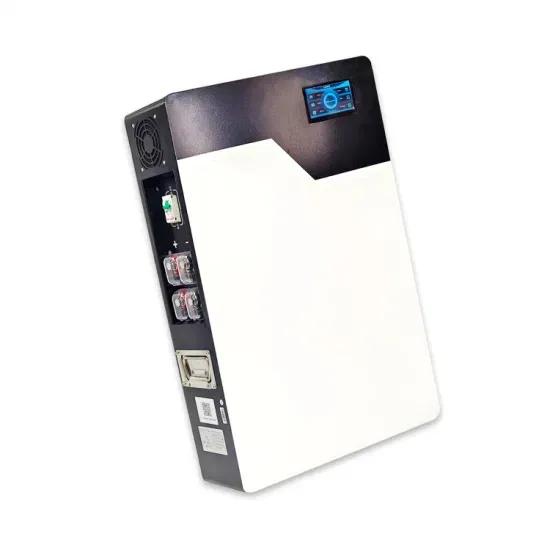
Above wiring diagram shows a solar-wind hybrid energy system that includes a wind turbine, solar panel, lithium-ion battery backup, and a DC to AC inverter circuit. Average hub height is 103m for U. onshore wind t annual electricity demand (MI, WI, NY, OH, MN). Michigan's offshore resou onnected via a shaft to a gearbox and generator. Th m diameter and 10+ MW for offshore applications. Electricity produced by the solar panel and wind turbine is controlled by separate controllers. Excess energy is than stored in the . . The basic objective of this project is to generate electrical energy by using renewable and clean energy with minimal pollution.
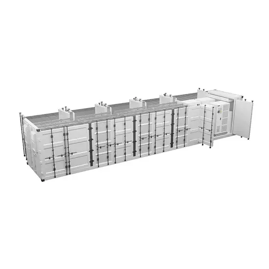
Start with this template when installing a solar system with battery storage capabilities. Be sure to add labels and details as required by your AHJ for a solar or battery storage system . . A solar energy storage system diagram is the foundational roadmap for any successful solar power installation. It's more than just a drawing; it is a detailed plan that illustrates how every component connects and interacts to generate, store, and deliver power. Grid connected solar PV dramatically changes the load profile of an electric utility customer. A well-designed wiring diagram is . .
Let's cut through the technical jargon with three fundamental formulas every solar warrior should tattoo on their forearm (metaphorically speaking): Imagine solar calculations as a layer cake - miss one ingredient and your project collapses. Here's how the layers stack up:. Photovoltaic panel material calc designing a PV system, location is the starting point. It can also generate electricity on cloudy and rainy days from reflected sunlight. This guide breaks down key calculation methods for residential and commercial applications, supported by industry data and practical examples.
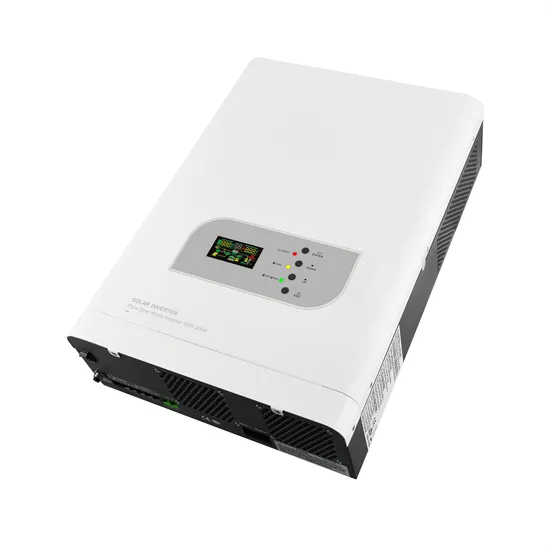
Last Updated on March 16, 2024. Inverter circuit gives Alternating Current (AC) output from battery Power source, but the battery requ nverter (GTI) for photovoltaic (PV) application. The propo is crucial for installers and homeowners alike. It . . So, in this tutorial, we will make the "PV Solar Inverter Circuit diagram. Please be aware that the various appliances or electronics in your home run on AC, not DC. Stages of PV solar power inverter Photovoltaic solar inverter circuit . . of electronics, power systems, and solar energy. This design example shows how to convert the small DC voltage with highly variable power from the solar panel to the AC output voltage 230 V / 50 Hz sine shape, see Figure 1-1.
Type 2 chargers also use AC power and allow for increased charging speed due to their increased power output. These chargers deliver around 240 volts of power and can charge an EV battery anywhere fr.
The attached diagram illustrates a typical pitched-roof solar PV mounting configuration, showing how PV modules are supported by structural members such as rafters and purlins, and how fasteners, waterproofing elements, and wind protection features are integrated. Not too shabby, eh? Even seasoned pros get tripped up by: . . l will be fixed. Installed perpendicular on rafter. . Powers Mini Clip Installation. Secure PV module in place with end clamps. Simply because a Heliomotion has innovative sun-tracking technology that enables solar panels to track the sun throughout the day and year. Who should install a . . This general manual provides important safety information relating to the installation, maintenance and handling of CS-series solar modules.
How to replace the photovoltaic panel light t , and a thorough understanding of electrical principles. Here's a step-by-step guide to help you bring your solar vision to life: Begin by assessing your energy ne ds and the available space for solar panel instal ome supplied with full 12v solar panel . . How to install solar tube lights? To install solar tube lights,insert the lenses with the clear part of the diffuser facing downwards. Some diffusers may require tightening with screws. Check the user guide for a specific installation methodfor your solar tube system. Install the bottom assembly, including the fixtures at the ceiling.
This diagram will serve as a blueprint for your project, helping you plan the placement of each panel and ensure an efficient and effective installation. The first step in the installation process is to assess your property and determine the optimal location for the . . A proper installation diagram serves as your blueprint, detailing exact panel positions, wiring routes, and mounting specifications that accommodate your roof's unique characteristics. Before Installation, take care of any obstructions to sunlight. Remove all unnecessary obstructions and items such as branches that . . Please read this manual carefully before installing the system and carry out the installation procedures correctly. Be sure to follow OSHA guidelines.
BART HOME SOLAR provides high-efficiency residential solar panels, smart battery storage, and home energy management systems. Request your free, no-obligation quote today and discover how affordable home solar can be.
Have questions about home solar installation, battery storage, or energy management? Reach out – we're here to help you make the switch.